
After building up our device (please see 1st part), we can start writing the code (called “sketch”) for the platform. Firstly, we should download and install the software for Arduino (you can easily find it on-line at https://www.arduino.cc/en/Main/Software?). After installing the software, we can take some confidence with Arduino, for example turning on and of the LED of the Arduino board. Connect the device to the PC. Open the Software and go to “Tools”>”Select port”> and select your Com-Port where Arduino is connected. Sequentially, go to “File”>”Examples”>”0.1Basic”>”Blink”. Have a look to the sketch: it describes a code to make the incorporated LED of Arduino blinking uninterruptedly every second. At this point, we can charge the sketch on the device (click on the arrow just below “File”) and see what happen. It always good to check the sketch before charging it (click on the “V” symbol just below “File”). If it’s working, we can move to our temperature recording sketch. (You can go to https://www.arduino.cc and find tons of interesting and useful tutorials).
Before writing the sketch, we should download the specific libraries (i.e. specific codes) of all the components. Just google them and download:
| What to download: | |
| Temperature library 1 | OneWire.h |
| Temperature library 2 | DallasTemperature.h |
| SD library | SD.h |
| LCD library | PCF8574_HD44780_I2C.h |
After downloading the files, extract the libraries in the Arduino folder called “libraries” (normally you can find it in the Documents Folder: C:\Users\Documents\Arduino\libraries). If you are very expert in Arduino, you can write your own libraries.
Finally, we can start writing the sketch for our device (the green colour sentences starting with “//” are comments, and do not affect the sketch; in the Arduino software are grey coloured):
| #include <PCF8574_HD44780_I2C.h> //this is to add the LCD library
#include <OneWire.h> //this is to add one of the library of the temperature sensor #include <DallasTemperature.h> //this is to add the other library of the temperature sensor #include <SD.h> //this is to add the LCD library
#define DS18B20 2 //this is to state where the T sensor is connected. In our case, pin number 2.
const int chipSelect = 10; //Pin where CS of SD card reader is placed (depends on the board, in most cases, such in our, pin 10) int secoon=0;//Defining the starting value of second, hours, minutes. Nothe that Secoon is the tot time the board is on int hour=0; int minutes=0; int seconds=0; int count=0; int timing=10000; //timing of counts. Every how many milliseconds we want to record the temperature (herein 10 seconds). We should add to this value, the delay value
PCF8574_HD44780_I2C lcd(0x27,16,2); // details of the LCD
OneWire ourWire(DS18B20); // Setup a oneWire instance to communicate with the T sensor DallasTemperature sensors(&ourWire); // Pass our oneWire reference to Dallas Temperature
//herein we start the loop void setup() { Serial.begin(9600); delay(1000); // wait one second, important to stabilize the device lcd.init(); // LCD ON lcd.backlight(); // Backlight of LCD ON while (!Serial) { ; } Serial.print(“SD control..”); pinMode(10, OUTPUT); if (!SD.begin(chipSelect)) { Serial.println(“Error”); return; } Serial.println(“Starting recording”); // This is the starting message you will see in the produced excel file File dataFile = SD.open(“datalog.csv”, FILE_WRITE); // This is the name of the file you will save if (dataFile) { dataFile.print(“TRIAL 1”); // This is the name of sequence dataFile.print(“;”); dataFile.println(“”); dataFile.println(“”); dataFile.println(“”); dataFile.print(“”); dataFile.print(“;”); dataFile.print(“Time h:m:s”); dataFile.print(“;”); dataFile.print(“Temperature C”); dataFile.println(“;”); dataFile.close(); delay(counts); }}
void loop() { secoon=millis()/1000; // Setting timing parameters hour=secoon/3600; minutes=secoon/60-hour*60; seconds=secoon-minutes*60;
File dataFile = SD.open(“datalog.csv”, FILE_WRITE);
int err; lcd.setCursor(0,0); // this is the coordinates of the LCD lcd.print(“Time:”); // this is what you want to write on the LCD lcd.print(millis()/1000); lcd.setCursor(0,1); sensors.requestTemperatures(); lcd.print(“T:”); lcd.print(sensors.getTempCByIndex(0)); lcd.print(” C “); delay(1000); dataFile.print(counts); dataFile.print(“;”); dataFile.print(hours); dataFile.print(“:”); dataFile.print(minutes); dataFile.print(“:”); dataFile.print(seconds); dataFile.print(“;”); dataFile.print(sensors.getTempCByIndex(0)); dataFile.println(“;”); dataFile.close(); // data save: Serial.print(counts); Serial.print(“;”); Serial.print(hours); Serial.print(“:”); Serial.print(minutes); Serial.print(“:”); Serial.print(seconds); Serial.print(“;”); Serial.print(sensors.getTempCByIndex(0)); Serial.println(“C”); delay(counts); conta++; //new count }
byte data[12]; byte addr[8]; |
Now we have to charge the sketch on our Arduino. Sequentially we can insert the micro SD card in the Arduino SD card reader and then turn off our device…..When we will turn on the device, the LCD will turn ON, and data will be recorded and saved in the micro SD!
Just try!
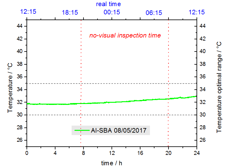
For example, these are the data with the device and manipulated with Origin 9:
Alessio Zuliani, University of Córdoba